Custom CNC Brackets & Adapters for Robotics
Integrating motors, sensors, and actuators into a functional robotic system requires precise mechanical interfaces. Off-the-shelf parts rarely provide the exact geometry, fit, or material properties necessary for custom frames or end-effectors.
RobotPartsCNC specializes in the precision CNC machining of brackets, adapters, and mounting plates for robotics and automation. We convert your CAD designs into functional hardware that ensures rigid, accurate alignment for your sub-assemblies, from one-off research prototypes to production runs of 500 units for an AMR fleet.
- Standard Tolerance
- ±0.01 mm
- Prototype Lead Time
- 3–7 days
- Axes Available
- 3 / 4 / 5
Precision Mounting Solutions for Robotic Systems
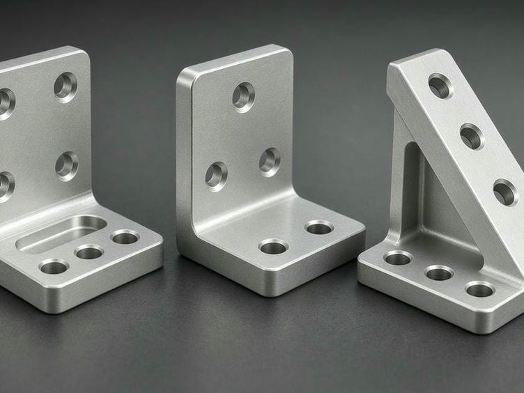
Brackets and adapters are critical to the structural integrity of any robot. Poorly machined mounts lead to vibration, misalignment, and sensor drift. We machine components that maintain precise positioning under operational loads.
Motor Mounts
High-rigidity plates designed to maintain precise gear mesh and shaft alignment across different motor frames.
Sensor & Camera Brackets
Lightweight, accurate mounts for LiDAR, depth cameras, and proximity sensors.
End-Effector Adapters
Custom interfaces for robot grippers, tool changers, and EOAT (End-of-Arm Tooling).
Structural Brackets
Gusseted or pocketed plates for robot arm joints and chassis reinforcement.
Drive & Bearing Housings
Precision bores for bearing fits and drive module integration.
Alignment Fixtures
Machined interfaces for assembly and calibration.
Manufacturing Capabilities
We utilize 3-axis, 4-axis, and 5-axis CNC equipment to handle complex geometries that standard machining cannot achieve. For brackets requiring features on multiple faces, our mill-turn and multi-axis capabilities reduce the need for multiple setups, improving positional accuracy and reducing cumulative tolerance errors.
Fast Turnaround, Small Batches
Rapid small-batch production for prototypes, pilot builds, and validated design iterations without long tooling lead times.
Precision Bores
Bearing fits and dowel pin holes held to micron-level tolerances.
Tight Geometric Tolerances
Control of flatness, perpendicularity, and parallelism for critical mating surfaces.
Thin-Wall Machining
Weight reduction for mobile robotics and aerial platforms without compromising rigidity.
Complex Pockets
Removing material to save weight while maintaining load-bearing paths.
Technical Specifications
A snapshot of the machining envelope we hold for robotics brackets, adapters, and mounting plates.
| Feature | Capability |
|---|---|
| Machining Methods | 3, 4, and 5-Axis Milling, CNC Turning |
| Standard Tolerance | ±0.01 mm |
| Tight Tolerance | Down to ±0.005 mm |
| Max Milling Size | 1000 × 600 × 600 mm |
| Surface Finish | Ra 0.4–3.2 μm |
| Prototype Lead Time | 3–7 working days |
| Production Lead Time | 7–20 working days |
| File Formats | STEP, STP, IGES, X_T, DWG, PDF |
DFM and Material Selection
Engineering a bracket involves balancing weight, strength, and machinability. Our team reviews your CAD models before production to identify potential issues such as deep pockets, inaccessible internal radii, or tolerance stack-up risks.
We can also coordinate secondary processes such as hard anodizing for wear resistance, or powder coating for environmental protection, ensuring your parts arrive ready for assembly.
Aluminum (6061-T6, 7075-T6)
The primary choice for most robotics brackets due to its excellent strength-to-weight ratio and ease of machining. 7075-T6 is recommended for high-stress applications.
Stainless Steel (303, 304, 316)
Used for medical or food-grade automation where corrosion resistance is required.
Engineering Plastics (POM, PEEK)
Ideal for lightweight, non-conductive, or low-friction mounting components.
From Prototype to Production
We support the full product development lifecycle. If you are iterating on a new humanoid joint or a custom gripper design, we can machine small quantities to verify the fit and function of your assembly. Once your design is validated, we optimize our machining processes—including fixture design and batch inspection—to scale up to production volumes while maintaining consistent quality.
-
1
Design Review
CAD model and DFM feedback before machining.
-
2
Prototype Verification
Small batches to validate fit and function.
-
3
Production Scale-Up
Fixture design and batch inspection for consistent quality.
Request a Quote
To get started, send your technical requirements to our engineering team. We review all drawings and models to provide accurate lead times and cost-effective manufacturing strategies.
Please include the following in your inquiry:
- 3D CAD files (STEP/IGES preferred)
- 2D drawings with GD&T specifications
- Material requirements
- Surface finish and inspection requirements
- Quantity
Contact Information
Email: info@robotpartscnc.com
Address:
Phone:
RobotPartsCNC provides the manufacturing infrastructure to turn your designs into reliable robotic hardware. Send your files today to begin the review process.